Multiplexer/Demultiplexer
Introduction
The multiplexer/demultiplexer component copies its input audio channels into output audio channels according to a specific routing matrix. Multiplexer has multiple input audio streams and a single audio output stream. Demultiplexer has a single input stream and multiple output streams. In the SOF codebase, multiplexer and demultiplexer are implemented in a single component as the operations and configurations overlap heavily.
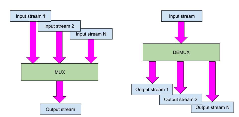
Figure 96 Multiplexer has exactly 1 output stream and demultiplexer has exactly 1 input stream.
Configuration
The component configuration defines how audio channels are copied from input to output streams. As the ASoC/SOF audio stream can have up to 8 audio channels, a stream-to-stream specific 8x8 routing matrix defines the channel mapping from input to output. Because every stream is fully configurable, we have a matrix for all multiplexer input streams or all demultiplexer output streams. The 8x8 binary matrix takes up to 64 bits and is controlled with eight unsigned char values.
Note
The mux/demux component can’t mix channels. If you try to set up mixing in the configuration matrix, you will get an error in the component initialization phase.
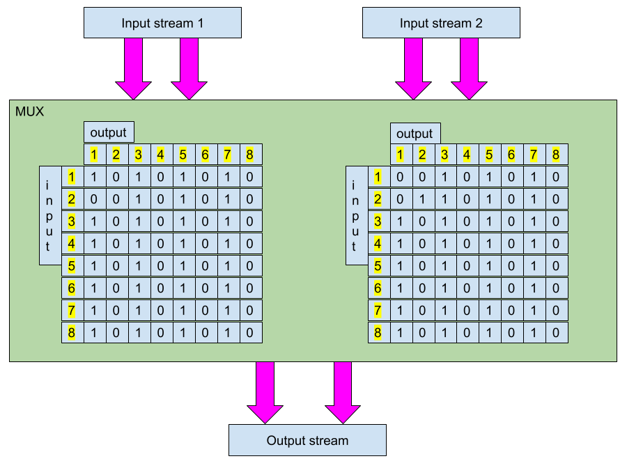
Figure 97 Example of multiplexer configuration matrices with 2 input streams. In this artificial mux example, the first input stream’s channel 1 is copied to the output stream’s channel 1. The second input stream’s channel 2 is copied to the output stream’s channel 2. If the streams have only 2 channels, the matrix values outside the 2x2 square don’t have any effect.
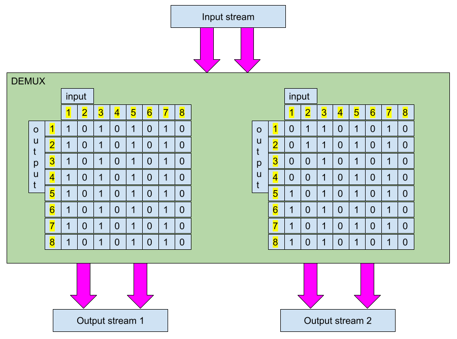
Figure 98 Example of demultiplexer configuration matrices with 2 output streams. In this artificial demux example, the input stream’s channel 1 is copied to both channels of the first output stream and the input stream’s channel 2 is copied to both channels of the second output stream.
Note
The demux matrix configuration is opposite to the mux configuration: the input channel is the matrix column and the output is the row.
Topology
Previous figures show that the routing matrix is difficult to parametrize in order to be easily understandable. As it is sent to firmware with 64 bits, it is quite tedious to easily see the binary routings from hexadecimal or integer values. SOF topology m4 macros have helpers to “visualize” the matrix for easier configuration.
The following example from pipe-volume-demux-playback.m4 shows how to define 2 routing matrices and a demux component:
# pipeline_id, channels, matrix_rows
define(matrix1, `ROUTE_MATRIX(PIPELINE_ID, 2,
                             `BITS_TO_BYTE(1, 0, 0 ,0 ,0 ,0 ,0 ,0)',
                             `BITS_TO_BYTE(0, 1, 0 ,0 ,0 ,0 ,0 ,0)',
                             `BITS_TO_BYTE(0, 0, 1 ,0 ,0 ,0 ,0 ,0)',
                             `BITS_TO_BYTE(0, 0, 0 ,1 ,0 ,0 ,0 ,0)',
                             `BITS_TO_BYTE(0, 0, 0 ,0 ,1 ,0 ,0 ,0)',
                             `BITS_TO_BYTE(0, 0, 0 ,0 ,0 ,1 ,0 ,0)',
                             `BITS_TO_BYTE(0, 0, 0 ,0 ,0 ,0 ,1 ,0)',
                             `BITS_TO_BYTE(0, 0, 0 ,0 ,0 ,0 ,0 ,1)')')

# pipeline_id, channels, matrix_rows
define(matrix2, `ROUTE_MATRIX(5, 2,
                             `BITS_TO_BYTE(1, 0, 0 ,0 ,0 ,0 ,0 ,0)',
                             `BITS_TO_BYTE(0, 1, 0 ,0 ,0 ,0 ,0 ,0)',
                             `BITS_TO_BYTE(0, 0, 1 ,0 ,0 ,0 ,0 ,0)',
                             `BITS_TO_BYTE(0, 0, 0 ,1 ,0 ,0 ,0 ,0)',
                             `BITS_TO_BYTE(0, 0, 0 ,0 ,1 ,0 ,0 ,0)',
                             `BITS_TO_BYTE(0, 0, 0 ,0 ,0 ,1 ,0 ,0)',
                             `BITS_TO_BYTE(0, 0, 0 ,0 ,0 ,0 ,1 ,0)',
                             `BITS_TO_BYTE(0, 0, 0 ,0 ,0 ,0 ,0 ,1)')')

# frame_format, num_channels, num_streams, route_matrix
MUXDEMUX_CONFIG(demux_priv, 2, 2, 2, LIST(`     ', `matrix1,', `matrix2'))

# demux Bytes control with max value of 255
C_CONTROLBYTES(DEMUX, PIPELINE_ID,
        CONTROLBYTES_OPS(bytes, 258 binds the mixer control to bytes get/put handlers, 258, 258),
        CONTROLBYTES_EXTOPS(258 binds the mixer control to bytes get/put handlers, 258, 258),
        , , ,
        CONTROLBYTES_MAX(, 304),
        ,
        demux_priv)

# Mux 0 has 2 sink and source periods.
W_MUXDEMUX(0, 1, PIPELINE_FORMAT, 2, 2, LIST(`         ', "DEMUX"))
In the above example you can see that the routing matrices have only “diagonal” 1’s, which means that input stream’s channels are copied to corresponding output streams channels.
ALSA control
Multiplexer configuration is loaded in the kernel/firmware boot as part of the ALSA binary control in topology, but can be also controlled through ALSA controls.
The complex binary control blob can be created with a generic python tool:
python sof_gen_blob.py -a 3 14 0 -t 18 -m 3H I 1B 8B 3B I 1B 8B 3B -v "2 2 2" "1" "2" "1 2 4 8 16 32 64 128" "0 0 0" "5" "1" "1 1 4 8 16 32 64 128" "0 0 0"
It produces the following output:
sof m4 and ALSA conf format:
`       bytes "0x53,0x4f,0x46,0x00,0x12,0x00,0x00,0x00,0x3c,'
`       0x00,0x00,0x00,0x00,0xe0,0x00,0x03,0x00,'
`       0x00,0x00,0x00,0x02,0x00,0x02,0x00,0x02,'
`       0x00,0x00,0x00,0x01,0x00,0x00,0x00,0x02,'
`       0x01,0x02,0x04,0x08,0x10,0x20,0x40,0x80,'
`       0x00,0x00,0x00,0x05,0x00,0x00,0x00,0x01,'
`       0x01,0x01,0x04,0x08,0x10,0x20,0x40,0x80,'
`       0x00,0x00,0x00,'

sof ctl tool format:
(4607827, 18, 60, 50388992, 0, 2, 2, 2, 1, 2, 1, 2, 4, 8, 16, 32, 64, 128, 0, 0, 0, 5, 1, 1, 1, 4, 8, 16, 32, 64, 128, 0, 0, 0)
The sof-ctl tool can be then used to set the parameters through ALSA control:
sof-ctl -Dhw:0 -n 22 -s demux_coeffs.txt